Site to Site VPN tunnel config between a Cisco ASA and a Juniper SSG ScreenOS
Below is a config to create a VPN tunnel between a Cisco ASA (Blue side) to a Juniper SSG ScreenOS (Red Side).
Juniper Settings:
ethernet0/0: 22.22.22.22, Untrust bgroup0: 172.16.22.1, Trust
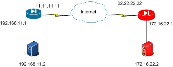
Cisco ASA config (Blue):
!^^^^^^^ ISAKMP (Phase 1) ^^^^^^^!
! must match with the other side in order for Phase 1 to complete.
! Lower policy numbers will likely be used before higher ones.
crypto isakmp policy 5
authentication pre-share
encryption aes
hash sha
group 2
lifetime 86400
! Enable ISAKMP on the outside interface
crypto isakmp enable OUTSIDE
! Define the pre-shared-key
tunnel-group 22.22.22.22 type ipsec-l2l
tunnel-group 22.22.22.22 ipsec-attributes
pre-shared-key sekretk3y
!^^^^^^^ IPSEC (Phase 2) ^^^^^^^!
! Define the interesting traffic in the ACL
access-list ACL-RED-VPN permit ip 192.168.11.0 255.255.255.0 172.16.22.0 255.255.255.0
crypto ipsec transform-set ESP-AES128-SHA esp-aes esp-sha-hmac
! Create a crypto map entry that defines the tunnel
crypto map MAP-OUTSIDE 20 set peer 22.22.22.22
! ACL must be exactly the opposite of the other sides ACL
crypto map MAP-OUTSIDE 20 match address ACL-RED-VPN
! Transform set must match other side identically
crypto map MAP-OUTSIDE 20 set transform-set ESP-AES128-SHA
crypto map MAP-OUTSIDE 20 set security-association lifetime kilobytes 10000
! Apply crypto map to an interface
crypto map MAP-OUTSIDE interface OUTSIDE
!^^^^^^^ Routes and No-NATS ^^^^^^^!
! Point the destination network out the outside interface with a next hop as the default gateway.
route OUTSIDE 172.16.22.0 255.255.255.0 11.11.11.1
! Make sure that the VPN traffic is NOT NATd
access-list ACL-INSIDE-NONAT extended permit ip 192.168.11.0 255.255.255.0 172.16.22.0 255.255.255.0
nat (INSIDE) 0 access-list ACL-INSIDE-NONAT
Juniper SSG-5 ScreenOS config (Red):
! Create a tunnel interface
set interface tunnel.1 zone Untrust
set interface tunnel.1 ip unnumbered interface ethernet0/0

# Create the gateway (IKE settings)
# note that "sec-level standard" means the IKE policies will try to use:  pre-g2-3des-sha and pre-g2-aes128-sha
set ike gateway "VPN-GATEWAY" ip 11.11.11.11 outgoing-interface ethernet0/0 preshare "sekretk3y" sec-level standard

# Configure VPN IPSEC settings
set vpn "VPN" gateway "VPN-GATEWAY" replay tunnel idletime 0 proposal "nopfs-esp-aes128-sha"
set vpn "VPN" id 1 bind interface tunnel.1
set vpn "VPN" proxy-id local-ip 172.16.22.0/24 remote-ip 192.168.11.0/24 "ANY"

# Configure a route for the remote end traffic
set vrouter trust-vr route 192.168.11.0/24 interface tunnel.1

# Create 2 address book entries and create two policies to permit this traffic
set address Untrust "192.168.11.0/24" 192.168.11.0/24
set address Trust "172.16.22.0/24" 172.16.22.0/24
set policy top from "Trust" to "Untrust" "172.16.22.0/24" "192.168.11.0/24" "ANY" Permit log count
set policy top from "Untrust" to "Trust" "192.168.11.0/24" "172.16.22.0/24" "ANY" Permit log count
Notes:
Coming at this from my Cisco background I had to learn some new ways of looking at this.
The traffic that can go over the tunnel is called the proxy-id. It is defined in the vpn settings. You also have to then permit this traffic in a policy between the two zones of your tunnel interface and whatever internal interface you have. In my case my Trust interface was bgroup0.
Troubleshooting:
Some show commands to see what’s going on:
get sa
get ike gateway
get event
Try creating a packet capture to see what is happening to the packet. With a packet capture you can see what is going on between the two VPN peers, or why your interesting traffic is not making it through the SSG.
clear db
set console dbuf
set ffilter src-ip 1.1.1.1 dst-ip 2.2.2.2
debug flow basic

# generate some traffic

# to see the capture:
get dbuf stream

# to stop capturing:
undebug all