Arduino Power Usage Project
I wanted to see how much power I am consuming in my home at any given moment, so I created this project using arduino. It features a simple display of LEDs: red representing high energy usage, yellow moderate usage, and green low usage.
Parts List:
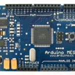
- Arduino Mega
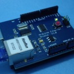
- Arduino EthernetShield V1.1
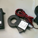
- TED 5000
- Linux Webserver
- 9 LEDs (with jumpers and resistors)
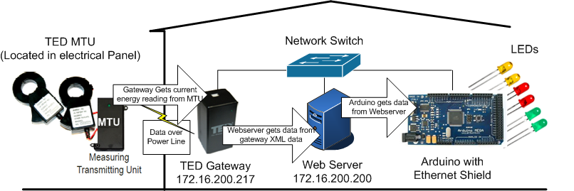
Diagram of how they all fit together:
STEP 1 - TED
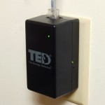
 Get TED (The Energy Detective) working at your house. This is a nifty little unit that has a device called an MTU that sits in your electrical panel to monitor your mains and how much electricity they use. Then it sends that data through the electrical wiring in your house to the gateway. The gateway then has an ethernet cable connected to to it and plugs into your home network.
The TED gateway makes a call every 5 seconds to get a reading from the MTU which is the device sitting in the main electrical panel. In my case, the TED gateway has an IP address of 172.16.200.216. Upon going to that website it has nice graphical display of real time power usage. The picture on the right is what the live kw usage shows on the TED software.
Upon doing some investigations with firebug I found that the website was drawing its information from an xml file called “/api/LiveData.xml”. This is the xml file that is updated every 5 seconds from the sensor outside. I examined the xml file and found the current power reading is within the
STEP 2 - PERL
Now I thought it would be smart for me to write a perl script on a server that basically goes to TED’s XML file that has the data I need and extract just that bit. I’m not very good with perl and just wanted something to get the job done so I apologize if this is ugly or isn’t effecient. I put this perl script in my cgi-bin directory of my webserver so it can be called remotely. Really the purpose of this is to scrub the data from the xml file and make this a much smaller input for the arduino. The xml file from TED was rather large for arduino to handle every 5 seconds. Here is the perl program I wrote.
#!/usr/bin/perl
use LWP::UserAgent;
use HTTP::Request;
my $agent = LWP::UserAgent->new(env_proxy => 1,keep_alive => 1, timeout => 30);
my $url = "http://172.16.200.217/api/LiveData.xml";
my $header = HTTP::Request->new(GET => $url);
my $request = HTTP::Request->new('GET', $url, $header);
my $response = $agent->request($request);

if ($response->is_success){
   print "Content-type: text/html\r\n\r\n";
   if ($response->content=~/<PowerNow>(\d*)<\/PowerNow>/) {
      print $1;
   }
} else {
 print "No response";
}
STEP 3 - ARDUINO
So now I just need the arduino to make a webcall to my webserver located at 172.16.200.200/cgi-bin/powerget.cgi and then display the LEDs depending on what value comes back. I wired the arduino to a breadboard with 9 LEDS. It looks like this.
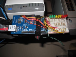
There are 3 green, 3 yellow and 3 red lights. More lights will light up depending on how much energy is being used. Key to reading lights:
- Below 100W
- Between 100-500W
- Between 500-1000W
- Between 1000-1500W
- Between 1500-5000W
- Between 5000-7500W
- Between 7500-10,000W
- Between 10,000-12,500W
- Above 15,000W
Arduino code:
#include <EtherShield.h>

#define HTTPPATH "/cgi-bin/powerget.cgi"
#define PORT 80
#define HOSTNAME ""  //unknown what this value is for yet
#define BUFFER_SIZE 550
byte buf[BUFFER_SIZE+1];
byte websrvip[4] = { 172,16,200,200 }; // set destination IP
byte mymac[6] = {0x54,0x55,0x58,0x10,0x00,0x25};
byte myip[4] = {172,16,200,77}; // Arduino's IP
byte gwip[4] = {172,16,200,2}; // Default gateway.
byte conn = 0; // used to track connections
int packetlength = 0; //used in loop
int powernow = 0; //global current value of power consumption
const byte numofLEDs = 9;
byte ledStates[numofLEDs];
const byte ledPins[numofLEDs] =  {23,24,25,26,27,28,29,30,31}; // the number of the LED pins
unsigned long timetosend;

EtherShield es=EtherShield();

void browserresult_callback(byte statuscode,word pos){
    // Get specific data from the web call (assuming power is never over 99,999W)
    char currentpower[5] = {buf[240], buf[241], buf[242], buf[243], buf[244]};
    // convert the string to an integer to do math on it
    powernow = atoi(currentpower);
    conn = 1; // If conn == 1 then the program knows the network connection worked
}

void setup(){

  es.ES_enc28j60Init(mymac); //initialize enc28j60

  //init the ethernet/ip layer:
  es.ES_init_ip_arp_udp_tcp(mymac, myip, PORT);

  // init the web client:
  es.ES_client_set_gwip(gwip);
  es.ES_client_set_wwwip(websrvip);

  // init the pins for LEDs
  for (byte i = 0; i < numofLEDs; i++) {
   pinMode(ledPins[i], OUTPUT);
  }

}

void loop()
{
  // handle ping and wait for a tcp packet
  // calling this routine powers the sending and receiving of data
  //defined as: uint16_t ES_enc28j60PacketReceive(uint16_t len, uint8_t* packet);
  packetlength = es.ES_enc28j60PacketReceive(BUFFER_SIZE, buf);
  es.ES_packetloop_icmp_tcp(buf,packetlength);

  if( millis() - timetosend > 5000) // every 5 seconds
  {
      timetosend = millis(); //this number should overload every 50 days or so...
      //request data from web server place data in buf[]
      es.ES_client_browse_url(PSTR(HTTPPATH), NULL , PSTR(HOSTNAME), &browserresult_callback);

      // reset all LEDs back to off
      for (byte i = 0; i < numofLEDs; i++) {
        ledStates[i] = LOW;
        digitalWrite(ledPins[i], ledStates[i]);
      }
      // Set which LEDs should be on
      if (conn == 1) {
        if ((powernow > 100) && numofLEDs>0) ledStates[0] = HIGH;
        if ((powernow > 500) && numofLEDs > 1) ledStates[1] = HIGH;
        if ((powernow > 1000) && numofLEDs > 2) ledStates[2] = HIGH;
        if ((powernow > 1500) && numofLEDs > 3) ledStates[3] = HIGH;
        if ((powernow > 5000) && numofLEDs > 4) ledStates[4] = HIGH;
        if ((powernow > 7500) && numofLEDs > 5) ledStates[5] = HIGH;
        if ((powernow > 10000) && numofLEDs > 6) ledStates[6] = HIGH;
        if ((powernow > 12500) && numofLEDs > 7) ledStates[7] = HIGH;
        if ((powernow > 15000) && numofLEDs > 8) ledStates[8] = HIGH;
      } else {
        // If network outage - turn on the top LED only to indicate a problem
        if (ledStates[numofLEDs-1] = HIGH);
      }
      conn = 0;

      // Turn on all the LEDs that need to be on
      for (byte i = 0; i < numofLEDs; i++) {
       digitalWrite(ledPins[i], ledStates[i]);
      }
  }
}
A few notes about using that ethernet shield with the arduino mega. First of all I used the Ethershield library located here: http://blog.thiseldo.co.uk/?p=504
Second, I had to hack ethernet board to get the two boards to talk to each other (this was really aggravating and I wish I had a different ethershield to work with). The hack I used was to bend certain pins that we don’t need to use and run jumpers to pins we do need to use. I followed the directions here to accomplish this: http://mcukits.com/2009/04/06/arduino-ethernet-shield-mega-hack/
Now unfortunately I still wasn’t done. The ethershield library thinks you have a duemilanove so I had to make one last adjustment.
In the file: enc28j60.h (usually found in arduino\libraries\EtherShield)
I changed the definitions for the SPI interface. Changed the ports to be as follows:
#define DEFAULT_ENC28J60_CONTROL_CS    53
#define SPI_MOSI                       51
#define SPI_MISO                       50
#define SPI_SCK                        52