Configuring HA on Juniper SRX through JunOS
This post will cover how to conduct HA (high availability) failover configurations for the Juniper SRX. This post will only cover a simple active/passive configuration. It will not cover more advanced deployments like layer 2 HA or active/active HA.
Requirements
- A maximum of 2 SRXs is allowed to be clustered at once.
- Both SRX devices must have matching hardware and software. This includes having matching modules in the same slots.
- This configuration requires the two SRXs to be directly connected to each other using two ethernet links. Generally these are simply normal ethernet ports that are on the SRX. One link is for control one link is for data.
- A reboot is required whenever putting a device into cluster mode or taking it out of cluster mode.
Goal of Active/Passive Failover Configuration
We will be using the diagram below to configure two SRX devices in Active/Passive failover mode.
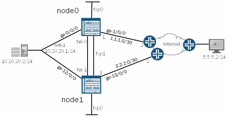
Terminology:
- node 0/node 1: Setting the node number distinguishes which SRX is which. Regardless of failover state, node 0 will always remain node 0 and node 1 will always be node 1. The firewalls can take turns being primary and secondary.
- fxp0: This interface is used to manage the devices.
- fxp1: This interface connects the two SRX’s together. This is called the ‘control-link’ and sends HA control data between the two SRXs including heartbeats and configuration synchronization. If this link goes down the secondary SRX is disabled from the cluster. It does this to avoid having 2 default gateways. To re-enable the secondary SRX you need to reboot the node. Each SRX model has a different port that is required to be used for fxp1. Review your systems documentation for details around that. Here is the documentation for SRX240 indicating the FXP1 port location.
- fab0/fab1: On both SRX devices is a fab port. These ports are known as the data links. The packets that are sent between the two SRXs on this port are called RTOs (real time objects). These objects contain session states.
- cluster-id: (Not displayed in diagram) The cluster-id is simply the number assigned to your cluster configuration. Cluster-id 0 is reserved. Any other number is valid.
- reth1: Redundant Pseudo Interface. A number of reth interfaces can be configured. This is a pseudo interface which will create a virtual mac address. It will normally contain 1 physical interface on each node which are called children nodes. When sending traffic to the reth interface IP, the traffic will be picked up by the primary node.
- RG0: (Not displayed) Redundancy Group. Within the redundancy group configuration is where weights and thresholds are configured that will trigger a failover event.
- interface names: The device used in the diagram is an SRX5800 with 2 FPC cards plugged into it. It has a maximum of 12 FPC slots. When connected in cluster mode, the standby unit’s interfaces will be +1 more than the max number of FPC slots in the primary. In this case the primary interfaces will be ge-0/0/0 to ge-0/0/11, ge-1/0/0 to ge-1/0/11 and the secondary will be ge-12/0/0 to ge-12/0/11, ge-13/0/0 - ge-13/0/11. If we were to plug another SPC into slot 12 of both SRXs it would then show up as ge-11/0/0 and ge-23/0/0.
In this diagram, when the host at 10.20.20.2 needs to get out to the internet it will have a default gateway of 10.20.20.1 which is the IP of the reth1 interface. The reth1 interface will be on whatever node is acting as primary. That node will then forward it’s packet out the internet interface to it’s destination. That stateful connection will then be transferred over to the secondary node. In the even the primary node goes down, the secondary node will assume the IP of the reth1 interface and become primary. It will already have it’s stateful connection table and configuration synced from the old primary node.
Configuration
Removing Interfaces and Hostname
Before configuring the HA, the SRX needs to remove the config for the host-name and the interfaces that are part of the fab, reth, fx1 and fx0 ports.
delete interfaces ge-0/0/0
delete system host-name
Setting up the Nodes
The following config will need to be added to both SRX boxes.
set group node0 system hostname srx1
set group node0 interfaces fxp0 unit 0 family inet address 10.99.99.1/24

set group node1 system hostname srx2
set group node1 interfaces fxp0 unit 0 family inet address 10.99.99.2/24

set apply-groups ${node}
The last command is run so that the individual configs for each node, set by the above commands, are applied only to that node. (required)
Enabling HA
Once the nodes are set up in the previous step that is all that is needed for the very basic HA configuration. Now we just need to reboot each box telling it to go into HA mode.
This is the step where the node is tied to the device. This command indicates the system the command was executed on will be that node number in the command.
Conduct on srx1:
user@srx1> set chassis cluster cluster-id 1 node 0 reboot
Conduct on srx2:
user@srx2> set chassis cluster cluster-id 1 node 1 reboot
Once they both reboot you can check the status by issuing the command:
show chassis cluster status
Cluster ID: 1
Node 					Priority				Status 		Preempt 	Manual failover

Redundancy group: 0, 	Failover count: 1
	node0					1 					primary		no 			no
	node1					1 					secondary	no 			no
Another show command is show chassis cluster interfaces which will indicate the status of the interfaces in the cluster.
Assign the Fabric Interfaces
At this point you will only need to conduct the configurations on the primary node. All configuration changes will be sync’d between both SRXs.
Connect the two SRX boxes together. In our example we’ll simply choose ge-0/0/3 on both boxes. Because it’s in cluster mode, the secondary SRX’s ge-0/0/3 will be ge-0/0/15. Both SRX’s have 12 ports in this case.
set interfaces fab0 fabric-options member-interfaces ge-0/0/3
set interfaces fab1 fabric-options member-interfaces ge-0/0/15
At this point, HA is on and the two SRX systems have their data link and control link up. Next we will make rules for determining when a failover will occur and then creating a pseudo interface to send traffic through the system.
Configure Redundancy Groups
By default RG0 is created which will monitor the routing engine of each SRX. However if there is a need to monitor the interfaces another RG can be created.
We’ll set up RG1 to monitor ge-0/0/0.
The formula for RG and failover is as follows:
RGx value = RGx threshold - interface weight
We’ll set the RG1 node0 threshold to be 200 and the interface to be 150. This means if that single interface goes down on node 0, the RG1 value will be 50, while the node 1 RG1 will be 100. Because of this new value the SRX cluster will failover. Because of this type of control, the admin can choose the exact scenario to cause a failover. By default the interface weight is 255.
set chassis cluster redundancy-group 1 node 0 priority 200
set chassis cluster redundancy-group 1 node 1 priority 100
set chassis cluster redundancy-group 1 interface-monitor ge-0/0/0 weight 150
RG0 refers to the routing engine. RG1 is created above.
Optional: Adjust the heartbeat intervals.
set chassis cluster heartbeat-interval <# of ms>
set chassis cluster heartbeat-threshold <# of intervals>
By setting the heartbeat levels will tune the firewalls to failover at a time you specify. A heartbeat will be sent out every # of milliseconds defined. If the firewall doesn’t hear from it’s mate after # number of intervals a failover will occur.
Configure reth1 as the Pseudo Interface
Now it’s time to create the reth1 interface. This is the interface will exist on whatever node is primary. First identify the physical interface that will be tied to reth1, then define the properties for reth1.
set interfaces ge-0/0/0 gigether-options redundant-parent reth1
set interfaces ge-12/0/0 gigether-options redundant-parent reth1
set interfaces reth1 description TRUST
set interfaces reth1 redundant-ether-options redundancy-group 1
set interfaces reth1 unit 0 family inet address 10.20.20.1/24
set chassis cluster reth-count 2
Note: The last command will tell the SRX to create 2 reth interfaces, reth0 and reth1. If we specified a reth-count of 3, it would then create a reth0, reth1 and a reth2 interface. We simply made 2 here because the diagram says reth1. If it said reth0 then we could have just had a count of 1.
At this point the SRX’s are configured in HA and have reth1 acting as the pseudo interface and the same IP will be present on whatever device is primary.
Add a Policy to reth1
You can create a policy and when you assign reth1 to a zone it will inherit those policies.
set security zones security-zone UNTRUST interfaces ge-1/0/0
set security zones security-zone UNTRUST interfaces ge-13/0/0
set security zones security-zone TRUST interfaces reth1.0
Routing for the UNTRUST
Since our UNTRUST interfaces are pointing to the internet and in our case 2 different carriers we can set some routing for this by having the preferred route be for node 0’s default gateway.
set routing-options static route 0/0 qualified-next-hop 1.1.1.2
set routing-options static route 0/0 qualified-next-hop 2.2.2.2 preference 10
At this point the two SRXs are configured for failover, and the primary is actively accepting packets for 10.20.20.1. This completes the failover configuration.
Show Commands
See what’s going on in the logs. Failover logs will show up in the JSRP (JunOS software Services Redundancy Protocol) logs.
show log jsrp
show chassis cluster status
show chassis cluster statistics
show chassis cluster interfaces
Traceoptions:
set chassis cluster traceoptions flag cli
set chassis cluster traceoptions flag configurations
set chassis cluster traceoptions flag heartbeat
Controlling the Cluster
Conduct a manual failover
request chassis cluster failover redundancy-group 1 node 1
Fail the units backover after a manual failover. This is called resetting the cluster.
request chassis cluster failover reset redundancy-group 1
Disable cluster (requires reboot). Do this to both nodes.
set chassis cluster disable reboot
From node 0, reboot node 1
set chassis cluster cluster-id 1 node 1 reboot
Further reading
Config generator to build HA configs from Juniper
Juniper KB on configuring clustering on an SRX
Juniper article: Understanding Failover
Juniper article: Understand Chassis Cluster Control Link Heartbeats